The Waste-to-Energy Process
At LCSWMA's Waste-to-Energy facilities, Municipal Solid Waste (MSW) is transformed using advanced technology, monitored by skilled operators from Reworld, a national leader in waste-to-energy technology. The video and case studies below illustrate the waste-to-energy process broken down into six steps:
01
Tipping and Sorting
Trucks unload the waste, which is inspected on the tipping floor and is pushed into a deep storage pit
02
Combustion
A grapple picks up the waste and feeds it into a boiler, combusting it and turning it into ash
03
Creating Steam
Water tubes surrounding our three boilers are heated until the water turns to steam
04
Energy generation
Steam spins a turbine that generates electricity for local homes and businesses
05
Metal recovery
Ash from the combustion process is put on a conveyor belt, and valuable metals are extracted for recycling
06
Ash reuse
Remaining ash is reused at the landfill for daily cover, reducing the need for soil and conserving landfill space
WTE CASE STUDIES
LCSWMA's Lancaster Waste-to-Energy Facility
Around 95% of Lancaster County’s municipal solid waste (MSW) is taken to the Lancaster Waste-to-Energy (WTE) Facility where it is combusted to create electricity.

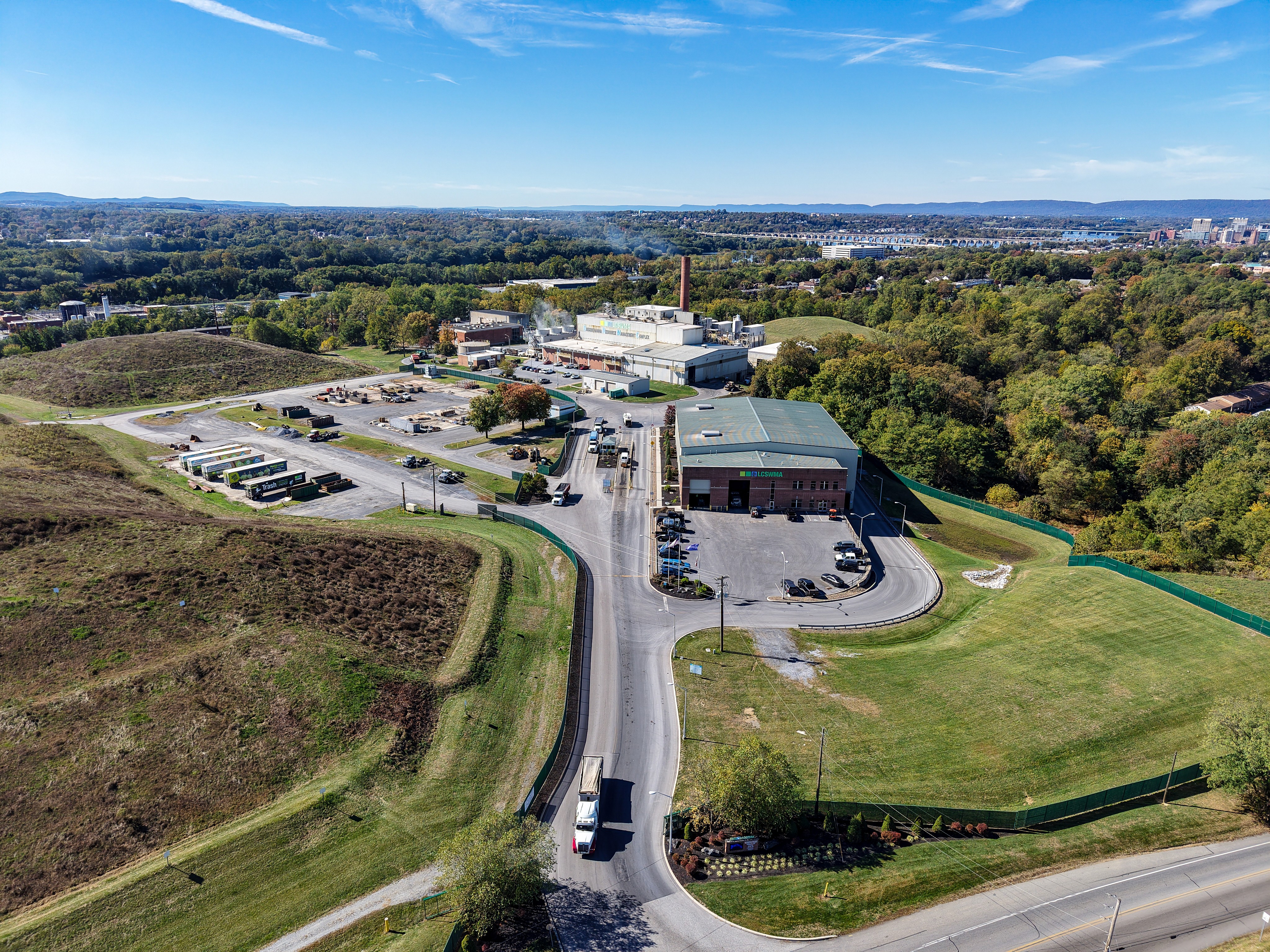
Harrisburg
Home to the country’s first waste-to-energy (WTE) facility, the Susquehanna Resource Management Complex (SRMC), offers an environmentally safe and sustainable means for disposing of waste while also generating clean, renewable energy.